I/O Addresses and I/O memory

/proc/ioports and /proc/iomem  Linux system files

/proc/ioports and /proc/iomem
Linux system files

Please note that this post follows on from : IRQ’s and Interrupts

I/O Addresses and I/O memory relate to bi-directional Communications between (CPU/Computer to devices ) as opposed to IRQ’s/Interrupt’s which are one way (device to CPU/Computer) communications.

Communication via I/O Addresses and I/O memory also relates to more general data transfers as opposed to Interrupts using IRQ’s which tend to relate to operational signals such as “I have finished Printing your document”.

The CPU writes data or maybe control codes to a devices (I/O port , I/O memory address).

Note that unlike Interrupts, this is not a one way communication process, the CPU can also use a device’s IO port to read status information about the device.

Like interrupts, ports and addresses should not be shared!

The Following is a good example of the Linux system file /proc/ioports

I/O ports in /proc/ioports

0000-001f : dma1
0020-0021 : pic1
0040-0043 : timer0
0050-0053 : timer1
0060-006f : keyboard
0070-0077 : rtc
0080-008f : dma page reg
00a0-00a1 : pic2
00c0-00df : dma2
00f0-00ff : fpu
0170-0177 : ide1
02f8-02ff : serial

The first column gives the I/O port address range reserved for the device listed in the second column.

I/O memory, /proc/iomem

System devices also need to have system memory allocated to them, devices such as the system RAM and GPIO ports .

The following is an example of the file /proc/iomem, taken from a Raspberry PI model 3

00000000-36ffffff : System RAM
00008000-007945ef : Kernel code
00804000-009497db : Kernel data
3f006000-3f006fff : dwc_otg
3f007000-3f007eff : /soc/dma@7e007000
3f00b840-3f00b84e : /soc/vchiq
3f00b880-3f00b8bf : /soc/mailbox@7e00b800
3f200000-3f2000b3 : /soc/gpio@7e200000
3f201000-3f201fff : /soc/uart@7e201000
3f201000-3f201fff : uart-pl011
3f202000-3f2020ff : /soc/sdhost@7e202000
3f215040-3f21507f : serial
3f300000-3f3000ff : /soc/mmc@7e300000
3f980000-3f98ffff : dwc_otg

The first column displays the memory used by each of the different types of registered device. The second column lists the details for the allocated memory.

This file tells the Linux Kernel system, where to find and store data that relates to the devices listed with in it.

Note : As with all Linux study, this information relates to a general perspective. You should take into account that Different versions of Linux May or May not do things in the orthodox fashion.

The Raspberry Pi using Rasbian Linux for example, does not have a /proc/ioports file available but does have the file /proc/iomem. Ubuntu Linux on a standard Intel PC has both /proc/ioports and /proc/iomem available to the system services.

You always have to dig deep when it comes to your own installation of Linux!

Advertisement
Posted in computer fundamentals, Linux, Operating systems, Uncategorized | Tagged , , , , , , , | Leave a comment

Device IRQ’s (interrupt requests) a Definition.

cropped-cropped-raspberry-pi2.jpg

Definition of : IRQ (interrupt request)

An IRQ (interrupt request) value is an assigned location in memory where the computer can expect a particular device to interrupt it when the device sends the computer signals about its operation.

Note that communication via Interrupts is a one way process (Device to Computer) !

For example, when a printer has finished printing, it sends an interrupt signal to the computer. The signal momentarily interrupts the computer so that it can decide what processing to do next.

Since multiple signals to the computer on the same interrupt line might not be understood by the computer, a unique value must be specified for each device and its path to the computer.

Prior to Plug-and Play (PnP) devices, users often had to set IRQ values manually (or be aware of them) when adding a new device to a computer.

If you add a device that does not support Pnp, the manufacturer will hopefully provide explicit directions on how to assign IRQ values for it. If you don’t know what IRQ value to specify, you’ll probably save time by checking the manufacturers web site or calling their technical support phone number for the device and asking them.

LINUX OS and IRQ’s

Linux keeps a map of all allocated IRQ’s in the /proc/interrupts file. You can view this file using an editor or use the following command to output its content to a terminal.

cat /proc/interrupts

as an example I have listed and saved the /proc/interrupts file from different computer systems, these being a (Toshiba L300 laptop, Radxa rock board and Raspberry pi( B+, B2 and B3)). You can see from the below listings that each type of system has very different devices installed and that some systems contain more helpful details in this “interrupts” file than others.

The Raspberry Pi systems for example show the starting memory address for the GPIO interrupts, yet the Radxa rock system only shows you the IRQ numbers for the configured GPIO devices that are using IRQ’s.

The below details then at the very least can help you see that you will have a very different path to take when it comes to writing code to control the same type of hardware on different devices, such as GPIO input and output hardware (LED’s for example !).


IRQ’s for a Toshiba L300

IRQ Num, CPU0, CPU1, details
0: 1608280 84979 IO-APIC-edge timer
1: 5054 109 IO-APIC-edge i8042
8: 0 1 IO-APIC-edge rtc0
9: 37955 82 IO-APIC-fasteoi acpi
12: 1950 68 IO-APIC-edge i8042
16: 0 0 IO-APIC-fasteoi uhci_hcd:usb3, uhci_hcd:usb7
18: 0 0 IO-APIC-fasteoi uhci_hcd:usb8
19: 0 0 IO-APIC-fasteoi ehci_hcd:usb1, uhci_hcd:usb6
21: 0 0 IO-APIC-fasteoi uhci_hcd:usb4
23: 104886 4581 IO-APIC-fasteoi ehci_hcd:usb2, uhci_hcd:usb5
42: 298749 54 PCI-MSI-edge eth4
43: 97179 17118 PCI-MSI-edge ahci
44: 240576 624194 PCI-MSI-edge i915
45: 27 30 PCI-MSI-edge snd_hda_intel
NMI: 14 20 Non-maskable interrupts
LOC: 705389 1336849 Local timer interrupts
SPU: 0 0 Spurious interrupts
PMI: 14 20 Performance monitoring interrupts
IWI: 32832 32161 IRQ work interrupts
RTR: 0 0 APIC ICR read retries
RES: 381401 345539 Rescheduling interrupts
CAL: 215 829 Function call interrupts
TLB: 240504 200521 TLB shootdowns
TRM: 0 0 Thermal event interrupts
THR: 0 0 Threshold APIC interrupts
MCE: 0 0 Machine check exceptions
MCP: 50 50 Machine check polls
ERR: 0
MIS: 0

IRQ’s for the Radxa Rock development board

IRQ num, CPU0, CPU1, CPU2, CPU3, details
32: 221 0 0 0 GIC rk29-pl330.1
33: 0 0 0 0 GIC rk29-pl330.1
34: 53855 0 0 0 GIC rk29-pl330.2
35: 0 0 0 0 GIC rk29-pl330.2
38: 0 0 0 0 GIC bvalid
41: 0 0 0 0 GIC vepu
42: 0 0 0 0 GIC vdpu
43: 0 0 0 0 GIC rk3066b-camera
46: 60525 0 0 0 GIC rk30-lcdc.1
48: 3565 0 0 0 GIC dwc_otg, dwc_otg_hcd:usb1, dwc_otg_pcd
49: 3970695 0 0 0 GIC dwc_otg, host20_hcd:usb2
51: 1753 0 0 0 GIC eth0
55: 41944 0 0 0 GIC rk29_sdmmc.0
57: 2 0 0 0 GIC emmc
58: 4804 0 0 0 GIC rk30-adc
71: 0 0 0 0 GIC rk29xx_spim
72: 0 0 0 0 GIC rk30_i2c.0
73: 8420 0 0 0 GIC rk30_i2c.1
74: 4176 0 0 0 GIC rk30_i2c.2
75: 121 0 0 0 GIC rk30_i2c.3
76: 21176 0 0 0 GIC rk_timer0
77: 0 6426 0 0 GIC rk_timer1
84: 596 0 0 0 GIC rk30_i2c.4
91: 0 0 4959 0 GIC rk_timer2
92: 0 0 0 6607 GIC rk_timer3
95: 0 0 0 0 GIC rga
112: 0 0 0 0 GIC debug-signal
164: 0 0 0 0 GPIO play
165: 0 0 0 0 GPIO bt_default_wake_host_irq
170: 27 0 0 0 GPIO remotectl
173: 0 0 0 0 GPIO rtc_hym8563
FIQ: fiq_glue
IPI0: 0 0 0 0 Timer broadcast interrupts
IPI1: 4559 4984 4185 7763 Rescheduling interrupts
IPI2: 19 32 32 28 Function call interrupts
IPI3: 17 59 232 98 Single function call interrupts
IPI4: 0 0 0 0 CPU stop interrupts
IPI5: 0 0 0 0 CPU backtrace
LOC: 0 0 0 0 Local timer interrupts
Err: 0

IRQ table for the Raspberry Pi B+

IRQ num, CPU0, details
3: 18089 ARMCTRL 3 Edge BCM2708 Timer Tick
16: 0 ARMCTRL 16 Edge bcm2708_fb dma
32: 138475 ARMCTRL 32 Edge dwc_otg, dwc_otg_pcd, dwc_otg_hcd:usb1
49: 0 ARMCTRL 49 Edge 20200000.gpio:bank0
50: 0 ARMCTRL 50 Edge 20200000.gpio:bank1
65: 16 ARMCTRL 65 Edge 2000b880.mailbox
66: 2 ARMCTRL 66 Edge VCHIQ doorbell
75: 1 ARMCTRL 75 Edge
77: 5535 ARMCTRL 77 Edge DMA IRQ
82: 746 ARMCTRL 82 Edge mmc0
83: 5 ARMCTRL 83 Edge uart-pl011
FIQ: usb_fiq
Err: 0

IRQ table for the Raspberry Pi B 2

IRQ num, CPU0, CPU1, CPU2, CPU3, details
16: 0 0 0 0 ARMCTRL 16 Edge bcm2708_fb dma
20: 0 0 0 0 ARMCTRL 20 Edge DMA IRQ
21: 0 0 0 0 ARMCTRL 21 Edge DMA IRQ
32: 106364 0 0 0 ARMCTRL 32 Edge dwc_otg, dwc_otg_pcd, dwc_otg_hcd:usb1
49: 0 0 0 0 ARMCTRL 49 Edge 3f200000.gpio:bank0
50: 0 0 0 0 ARMCTRL 50 Edge 3f200000.gpio:bank1
65: 36 0 0 0 ARMCTRL 65 Edge 3f00b880.mailbox
66: 2274 0 0 0 ARMCTRL 66 Edge VCHIQ doorbell
75: 1 0 0 0 ARMCTRL 75 Edge
77: 5487 0 0 0 ARMCTRL 77 Edge DMA IRQ
79: 0 0 0 0 ARMCTRL 79 Edge 3f804000.i2c
80: 0 0 0 0 ARMCTRL 80 Edge 3f204000.spi
82: 520 0 0 0 ARMCTRL 82 Edge mmc0
96: 0 0 0 0 ARMCTRL 96 Edge arch_timer
97: 3336 3138 2762 2616 ARMCTRL 97 Edge arch_timer
FIQ: usb_fiq
IPI0: 0 0 0 0 CPU wakeup interrupts
IPI1: 0 0 0 0 Timer broadcast interrupts
IPI2: 10445 12060 18171 14350 Rescheduling interrupts
IPI3: 10 16 16 13 Function call interrupts
IPI4: 32 43 67 202 Single function call interrupts
IPI5: 0 0 0 0 CPU stop interrupts
IPI6: 0 0 0 0 IRQ work interrupts
IPI7: 0 0 0 0 completion interrupts
Err: 0

IRQ table for the Raspberry Pi B 3

IRQ num, CPU0, CPU1, CPU2, CPU3, details
16: 0 0 0 0 ARMCTRL 16 Edge bcm2708_fb dma
20: 0 0 0 0 ARMCTRL 20 Edge DMA IRQ
32: 12410673 0 0 0 ARMCTRL 32 Edge dwc_otg, dwc_otg_pcd, dwc_otg_hcd:usb1
49: 0 0 0 0 ARMCTRL 49 Edge 3f200000.gpio:bank0
50: 0 0 0 0 ARMCTRL 50 Edge 3f200000.gpio:bank1
65: 1494 0 0 0 ARMCTRL 65 Edge 3f00b880.mailbox
66: 2 0 0 0 ARMCTRL 66 Edge VCHIQ doorbell
75: 1 0 0 0 ARMCTRL 75 Edge
77: 21849 0 0 0 ARMCTRL 77 Edge DMA IRQ
82: 14846 0 0 0 ARMCTRL 82 Edge mmc0
83: 4962 0 0 0 ARMCTRL 83 Edge uart-pl011
84: 753993 0 0 0 ARMCTRL 84 Edge mmc1
96: 0 0 0 0 ARMCTRL 96 Edge arch_timer
97: 558639 362236 427497 330519 ARMCTRL 97 Edge arch_timer
FIQ: usb_fiq
IPI0: 0 0 0 0 CPU wakeup interrupts
IPI1: 0 0 0 0 Timer broadcast interrupts
IPI2: 351505 410401 258035 378912 Rescheduling interrupts
IPI3: 5 10 10 11 Function call interrupts
IPI4: 7 142 88 58 Single function call interrupts
IPI5: 0 0 0 0 CPU stop interrupts
IPI6: 0 0 0 0 IRQ work interrupts
IPI7: 0 0 0 0 completion interrupts
Err: 0

The first column refers to the IRQ number. Each CPU in the system has its own column and its own number of interrupts per IRQ. The next column reports the type of interrupt, and the last column contains the name of the device that is located at that IRQ.

The first two tables are interesting as they show you the difference between the types of devices installed on a more traditional pc and those of a ARM CPU based development board such as the Radxa Rock.

Some of the devices listed are easier to identify than others e.g.

e.g. for the Radxa rock :

43: 0 0 0 0 GIC rk3066b-camera

This very clearly shows that IRQ 43 is allocated as the interupt for the rk3066b-camera module that can be plugged into the Radxa Rock camera port.

Other devices on the Radxa rock, such as :

173: 0 0 0 0 GPIO rtc_hym8563

are a lot less clear as to what they are, two great sources to find out are the Radxa rock peripherals Manual , or just browse the web for this device name, “rtc hym8563” for example.

As a final note for this post!, you may have noticed that on the Raspberry pi systems there is a listing of three lines for GPIO IRQ’s as follows

Raspberry Pi B+

49: 0 ARMCTRL 49 Edge 20200000.gpio:bank0
50: 0 ARMCTRL 50 Edge 20200000.gpio:bank1
65: 16 ARMCTRL 65 Edge 2000b880.mailbox

Raspberry Pi 2

49: 0 0 0 0 ARMCTRL 49 Edge 3f200000.gpio:bank0
50: 0 0 0 0 ARMCTRL 50 Edge 3f200000.gpio:bank1
65: 36 0 0 0 ARMCTRL 65 Edge 3f00b880.mailbox

Raspberry Pi 3

49: 0 0 0 0 ARMCTRL 49 Edge 3f200000.gpio:bank0
50: 0 0 0 0 ARMCTRL 50 Edge 3f200000.gpio:bank1
65: 1494 0 0 0 ARMCTRL 65 Edge 3f00b880.mailbox

from these details you can extract the simple fact that the IRQ physical memory address (given in HEX DECIMAL!)for the GPIO devices of (GPIO-BANK1 and 2, GPIO-mailbox) changed their addresses from models B+ to B2 but did not change form the Raspberry Pi b2 to b3!

NB : A future area for study relating to IRQ’s is to detail exactly how system software uses these IRQ/Interrupts but for this post this is just about the correct amount of information.

More reading on Irq’s and Interrupts

Note : This post is followed in study order by: I/O Ports and I/O memory

Posted in Development board hardware, Linux, Radxa rock, Raspberry pi, Single board computers, Uncategorized | Tagged , , , , , | Leave a comment

Introduction to the new “Study Notes section”

New Study Notes section

New Study Notes section

Introduction of the Study Notes section

I have been feeling the need on my blog to create a general study notes section, so today this is what I am doing. I find that there are general IT related topics that are getting lost in posts that relate to much bigger areas but I need these sub-skills to be easier to locate here as they themselves relate to multiple technical areas.

This new links section on the right hand side of the screen is simply titled “Study notes”, it will contain posts that relate to single study topics.

The reason for this new area of posts is that I feel a need to record notes on smaller technical areas as I perform my own areas of more complete – hardware and software study.

You can locate this new area at the very bottom of the links panel, right of this screen !

Posted in Introduction, Study guides and exams | Tagged , , , , , | Leave a comment

ARM Development boards and their low-level coding Data-sheets

Development Board GPIO

Development Board GPIO

BCM2837-SoC-auf-Raspberry-Pi-3

Low level Arm Processor Development

Starting to get to grips with coding on any computer system is not a simple task. At the very start you need to select an appropriate coding language and then choose the best possible learning method and path to follow.

Most likely the most common way is to select the middle ground, one that is not too advance in its low level of closeness to the actual hardware of the computer, using machine code instructions and also one that is not to advanced in the world of object orientated methods.

Machine code programming along with Assembly language programming is not only a very difficult and time consuming way to learn to program, it is also not a requirement of any kind and not needed in order to develop projects on single board computers like the Raspberry pi.

However the process of learning just how your computer system truly works under the hood is great fun and will give you a greater sense of overall control, when you are doing your best to create well written and fully debugged code.

Following on from my last post on single board computer electronics project code development, at the end of the post I said I would move forward by following a path as follows :

1.. Looking at any available GPIO information from the Broadcom BCM2835-ARM-Peripherals manual and Radxa Rock Rockchip RK3188 CPU Datasheet

2.. A Look at how the Raspberry PI operating systems are configured to control the GPIO port, its pins and its operating system interfaces.

3.. Construct a full review in a series of posts, of all available GPIO enabled programming languages starting with Python and followed by languages such as C++ and Java.

Well firstly you can down load these datasheets and technical PDF’s at these links.

Raspberry Pi Broadcom BCM 2835/ Radxa Rock Rockchip RK3188 Datasheets

Broadcom BCM2835 ARM Peripherals

Rockchip

Rockchip RK3188

Firstly You need to understand that these manuals in the form of datasheets, are just like reading the Linux MAN pages, they are coldly technical and contain little in the way of help in actually developing applications that make use of their details.

Always download these manuals or the Datasheet/Manual that relates to your own system and its CPU and Devices but remember they are for reference only.

In order to start to make use of the details contained within, you will need to gain some help with Machine code or Assembly language coding itself and then start to bring in to this preliminary knowledge the technical details that relate to your own system.

Here are two links that will help you make a start, I have followed this path !

1.. ARM assembler in Raspberry Pi, this is a great starting point !!!

2.. RaspberryPi.org Assembly language guides

3.. Amazon Books

IN ALL HONESTY !!!,

This path is a rocky and hard one and you will fall off it into deep water many times !, one of the most noticeable potholes relates to the fact that for systems such as the Rasberry PI, most of the available information only relates to the model B boards and not the newer (B+ 2b and new 3b), many web based locations have not updated since the model B , yet they do not say clearly so !! , before you order a book or read a web page make sure it relates to your own model or check you are willing to learn from older models and then do the needed work to move forward !

e.g Baking Pi – Operating Systems Development , Here they do at least say that their operating system project has not been updated !!

There could be many reasons for this being the case, one possibly being the work and man hours that is needed to port very detailed low-level code from one version of the Raspberry pi to another (or any platform!). In this simple fact lies the basic problem with assembly language, you need to re-work your code for each system and take into account each of the technical changes within CPU versions.

The Answer and trick here is to wait and hold on, in time much more details about a newer system do get released to the general public or finds its way onto forums and blogs, this is a learning process ok and this can also include the developers. The other trick once you do get your much needed details is to make sure you check if they are correct and test them to work, then make and keep some good notes.

It is also this problem that correctly moves coders up the scale in their selection of development methods, they select a development path that makes use of higher level languages such as (C++, Java or Python) as examples. One great reason for doing so is that it is left to the developers of the C++ language for example, to include all the needed details with in the source compiler for the hardware it is being aimed at.

Hardware developers also release C++ libraries or PYTHON modules that can be incorporated into your source code.

To make use of a High level language thus removes you from needing to know all the low-level details, also meaning that very few people are producing the low level code used in higher level language hardware related functions, thus reducing the number of possible errors and bugs in your finished applications. This is good Right !!!

Despite all this though, it is still great fun to learn what your CPU is actually doing and like I already said very enabling if you can get to grips with all the needed details.

For the moment in my posts, I will move along my path as I detailed earlier , I will however return to Assembly language development as I personally enjoy it and feel its a great learning experience !

Posted in computer fundamentals, Development boards, Development Languages, Radxa rock, Raspberry pi, Software | Tagged , , , , , , , , , , , | Leave a comment

Raspberry Pi light sensor controlled LED lamp Project

Raspberry PI LED lamp and Light sensor project

Raspberry PI
LED lamp and Light sensor project

Project Plans and notes

I am currently working on a background PI project to replace the on/off switch on a desktop LED lamp that I needed to repair.

The Lamp is made by electronics company called “AM Tech” and cost as little as €9, it can be powered by AA batteries or a 5v adaptor.

I have by-passed the power switch by connecting the LED panel in the head of the lamp to my Raspberry Pi via a project breadboard. I have then started to control this lamp using some python code with the lamps positive connection attached to GPIO pin 17 on the Raspberry Pi header with the negative side of the circuit to a GRD pin.

The next stage of this project is to control the turning on and off of the lamp via a light sensor so that it can be used to light my desk only when the room light falls below the level I need to read.

I also have some other fun projects planed such a using the lamp to indicator such things as a “You have new mail” and “Active process”. It can also be used as a project debugging tool to show that the correct GPIO pins are active or not.

Posted in Development board hardware, Hardware construction, Python, Raspberry pi, Software | Tagged , , , , , , , | Leave a comment

Raspberry Pi GPIO programming

DSCF6353 - Copy

GPIO – Starting from the pins up

During the last week of study I have spent a lot of time looking at many online references that relate to Coding for GPIO input and output on the Raspberry PI along with my other single board computers including (Radxa rock, banana Pi and Odroid U3+).

As many programmers will know there are many walls to be climbed while following a path of reference using the web, this has been the case during the last week of my reading for sure.

Just taking the Raspberry Pi alone for the moment, the study blocks relate to the fact that a lot of web pages contain details that are incomplete or are just simply not tested and thus working. You need a lot of time and patience to work through to the point where you yourself have collected enough details that actually work when coded in reality.

I have however now reached a point where I can at least post the details that I have collected, feeling that they work as I have now tested them to do so !!

There is simply too much detail relating to GPIO coding to place in this post alone so here today I am just going to pass on the base ground work that I am willing to use myself, in order to work outwards from them to each of my possible coding routes.

In My last post I introduced the basic concept of GPIO input/output and ended by saying that I would in this post talk about how GPIO is controlled via programming languages.

There are many programming languages that you can install on the Raspberry PI and other GPIO enabled development boards but not all of them are matched well to code for GPIO, I feel that the reason for this is as follows.

GPIO coding has many levels some falling at the hardware level of Machine code and Assembly Language, others abstracted far away in the realm of object orientated programming methods.

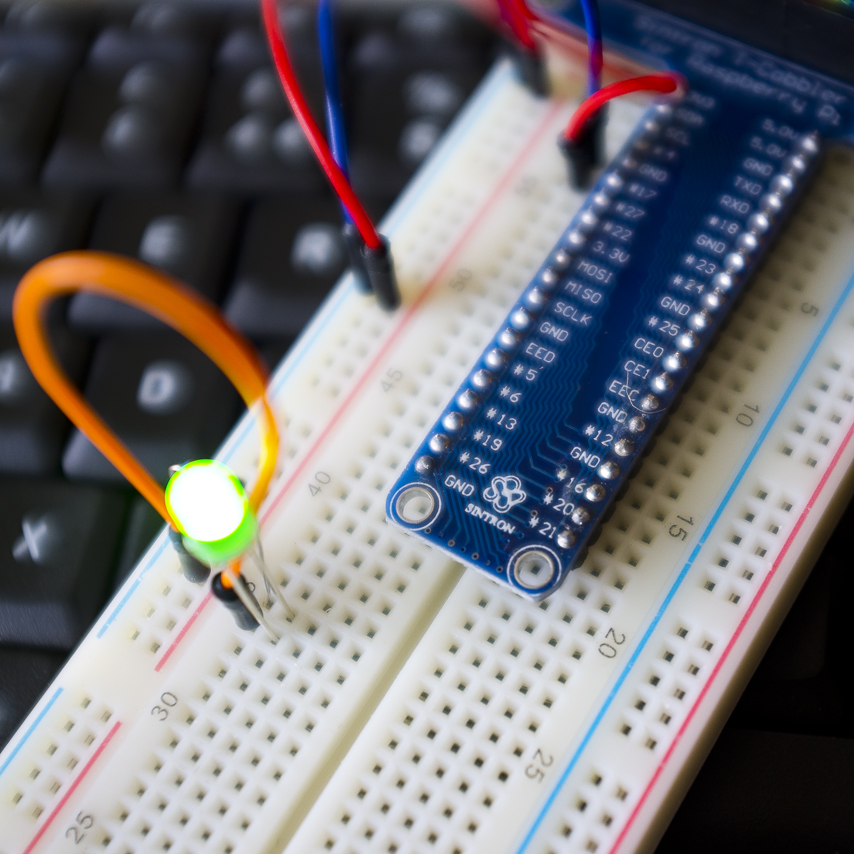
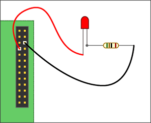
Here is an example of using assembly language to turn on an LED light :-

This example requires a simple wiring, using an LED and a resistor (1KOhm, typically) to 2 GPIO pins of the RaspPi 2 header. More information on the GPIO connector pinout can be found here. The black wire is connected to Pin 6 of the header (GND), and the red wire to Pin 7 (BCM 4)

RasPi2LEDWiring

Raspberry-Pi-GPIO-Layout-Model-B-Plus-rotated

Assembly Code by : D. Thiebaut

@ LINK !! blink.s
@ D. Thiebaut
@ based on the following C program:
@
@ #include
@ #include
@ #include
@
@ int main (void) {
@ int pin = 7;
@ printf(“Raspberry Pi wiringPi blink test\n”);
@
@ if (wiringPiSetup() == -1) {
@ printf( “Setup didn’t work… Aborting.” );
@ exit (1);
@ }
@
@ pinMode(pin, OUTPUT);
@ int i;
@ for ( i=0; i<10; i++ ) {
@ digitalWrite(pin, 1);
@ delay(250);
@
@ digitalWrite(pin, 0);
@ delay(250);
@ }
@
@ return 0;
@ }
@
@ To assemble, link, and run:
@
@ as -o blink.o blink.s
@ gcc -o blink2 blink.o -lwiringPi
@ sudo ./blink2

@ —————————————
@ Data Section
@ —————————————

.data
.balign 4
Intro: .asciz "Raspberry Pi wiringPi blink test\n"
ErrMsg: .asciz "Setup didn't work… Aborting…\n"
pin: .int 7
i: .int 0
delayMs: .int 250
OUTPUT = 1

@ —————————————
@ Code Section
@ —————————————

.text
.global main
.extern printf
.extern wiringPiSetup
.extern delay
.extern digitalWrite
.extern pinMode

main: push {ip, lr} @ push return address + dummy register
@ for alignment

@ printf( "blink…" ) ;
ldr r0, =Intro
bl printf

@ if (wiringPiSetup() == -1) {
@ printf( "Setup didn't work… Aborting." ) ;
@ exit (1) ;
@ }
bl wiringPiSetup
mov r1,#-1
cmp r0, r1
bne init
ldr r0, =ErrMsg
bl printf
b done

@ pinMode(pin, OUTPUT) ;
init:
ldr r0, =pin
ldr r0, [r0]
mov r1, #OUTPUT
bl pinMode

@ for ( i=0; i<10; i++ ) {
ldr r4, =i
ldr r4, [r4]
mov r5, #10
forLoop:
cmp r4, r5
bgt done

@ digitalWrite(pin, 1) ;
ldr r0, =pin
ldr r0, [r0]
mov r1, #1
bl digitalWrite

@ delay(250) ;
ldr r0, =delayMs
ldr r0, [r0]
bl delay

@ digitalWrite(pin, 0) ;
ldr r0, =pin
ldr r0, [r0]
mov r1, #0
bl digitalWrite

@ delay(250) ;
ldr r0, =delayMs
ldr r0, [r0]
bl delay

add r4, #1
b forLoop

done:
pop {ip, pc} @ pop return address into pc

———————————————————————

Follow the link at the top of the listing for more details !!

For sure Assembly Language is a very legitimate method of programming the Raspberry-pi or any computer of its type. It has the huge advantage of not even needing an operating system to be loaded when the raspberry pi boots, I will detail the methods of doing this when its appropriate to do so but for now just take it as a possibility for applications where only your machine code is needed, in projects that do not need an operating system, i.e. your TV has no OS! but plenty of code.

NB : As a related foot note – you can do the same as above using compiler based languages that can produce stand-alone machine code routines.

It is at this level of hardware programming that everything starts when it comes to coding for GPIO, the level of direct memory addressing for both input and output. Above this level you will find that all GPIO enabled programming languages follow two routes!

Firstly they can make use of the operating system to control any devices attached to the GPIO pins, Linux and on the Raspberry PI2 and 3, Windows 10 for IOT, are both configured to allow for GPIO pin control or device driver control for hardware devices that are attached as peripherals to the GPIO port.

Secondly languages can make use of code (libraries, units or modules ) that bypass the operating systems GPIO configuration in order to just like the Assembly language example here directly read or write to the pins on the GPIO header.

I feel this is just about the correct amount of information for this post today, my following posts will be a series of posts that will take the form of study notes that follow a route as below :

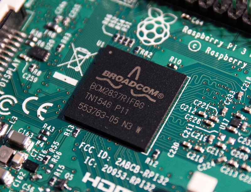
1.. Looking at any available GPIO information from Broadcom BCM2835-ARM-Peripherals Datasheet , Broadcom Publish a datasheet. The purpose of this datasheet is to provide documentation for all SOC peripherals in sufficient detail to allow a developer to port an operating system to BCM2835.

I have now posted relating to this area here….

I may also contrast and compare this information to that of datasheets available for the Radxa rock and Odroid U3 systems.

2.. A Look at how the Raspberry PI operating systems are configured to control the GPIO port, its pins and its interfaces. The reason for this post will be centred around the fact that you can use the operating system itself to code in the form of shell scripts. All GPIO enabled versions of Linux for the Raspberry Pi and other boards such as the Radxa rock use a file structure in the mounted file systems to pass read and write (input and output) signals to the shell, these signals can be used in a shell script.

Not to cloud issues but it is even possible to use none GPIO enabled programming languages to code for GPIO, if they can open and write to and read from these operating system files, I do however only want to make use of fully GPIO capable languages and their GPIO libraries and modules!

I have now posted relating to this area

3.. I want to construct a full review (that will involve more than one post!) of all available GPIO enabled programming languages starting with Python and followed by languages such as C++ and Java. I have found in the Radxa rock and some Raspberry Pi documentation that included coding examples, only involve – as I said above, opening and closing the related operating system files. To do this is most likely very slow and inefficient and also has the drawback of not producing stand-alone code. While this kind of code is more than ok for testing purposes ! why not work with the final aim of your code being fast and also having the ability to run itself in such away that it can be loaded in any environment with or without needing a particular OS or even one at all !!

Ok that really is enough for this post, back soon !!

Posted in Development board hardware, Development Languages, Linux, Operating systems, Radxa rock, Raspberry pi, Uncategorized, Windows 10 IOT core | Tagged , , , , , , , | Leave a comment

Raspberry Pi development projects and GPIO coding

DSCF6353 - Copy

Ever Since the launch in early 2015 of the Raspberry Pi 2 and followed one year later in early 2016 with the Pi 3, the Raspberry PI development board is now with out question a fully usable desktop computer, provided you just need it to perform any of the standard office and internet tasks performed in most peoples day to day requirements. So both of these models ( 2b & 3b ) perform very well for the operations of which any one buying a credit card sized computer could think of and expect to get.

The Raspberry Pi project however has always been aimed at educational needs in computer science, allowing for the needs of schools and higher education facilities. At its low price of €40 you can fill up the desks of students and allow them to experiment to their harts content, even if they damage them they are very simple to replace.

It is not only in the area of cost that the Raspberry Pi wins however, the fact is that this little computer is much more flexible than any desktop or laptop pc when it comes to the area of learning to intelligently program electronics based hardware devices.

Just like many of the available development board computers available today the Raspberry Pi systems allow you to not only communicate with recognised PC peripherals such as (Disks, printers, scanners, modems and screens) they also provide you with the ability to communicate at the lowest possible level with any electronic device that can be manually configured to connect to the Pi via the provided 40 pin GPIO connector on the Raspberry Pi Board.

Raspberry Pi

You can see this 40pin connector at the top of the PI board in the first of these two images. This is a Raspberry PI B+, the original Pi board in the current B series (B+, 2B and new 3B) Pi’s.

Raspberry-Pi-GPIO-Layout-Model-B-Plus-rotated

The GPIO enabled pins are designated a GPIO number as you can see in the second image here. I will in a later post come back to define the functions of all of these pins, if you enlarge and view this images however you will see that not all of the 40 available pins are in fact given a GPIO number, some being used to provide a positive current of (3.3v or 5v) and then other pins used as a Ground in order to complete a circuit.

The live (3.3v or 5V) pins and the Ground pins are used in one of the very simplest of electronic projects for the Raspberry Pi, the lighting of an LED. This is exactly what your pc or TV does when you first turn it on and can be used in the same way to show that your Raspberry PI is powered on.

The details of this project are HERE…

DSCF6352 - Copy

Just to show that this project works, you can see the LED lighting in the above image, my own project version using a breadboard 🙂

In my following post I want to examine how these GPIO pins and thus any attached device can be programmed using computer code.

It is possible to install any of the programming languages available in the Linux repository including (Basic, Ruby, Fortran, Lisp, Cobol, Python, Pascal and C++ …) however not all of these Languages have the facilities with in themselves to control GPIO pins , so I want to look at which ones have and how they can program GPIO input and output !!

Back very soon…

Posted in Development board hardware, Development boards, Development Languages, Linux, Raspberry pi, Single board computers | Tagged , , , , , , , , , , | Leave a comment

Raspberry Pi 7inch HDMI LCD screen and case, Setup and installation

Raspberry pi lcd screen nigel borrington20160405_0001

This week I received and installed one of the final elements for my Raspberry pi 3 project , a 7 inch LCD touch screen from Waveshare.com , this is a great addition to my Raspberry pi hardware. it can also be used with the Radxa Rock and Odriod development boards along as an additional HDMI Touch screen on a laptop or desktop.

My main aim for this additional device is to free up the Raspberry pi 3 from my main PC monitor and also allow my Raspberry PI 3 to be used for stand alone applications such as a network monitor or as a web server, in both cases using the screen to output monitoring information.

One of the great things about the Raspberry Pi is that because it uses the Linux OS, you can very easily using SSH or VNC connect to it remotely, I still intend to do this even with this screen. The screen however provides the additional ability to turn the PI into a stand alone workstation that can be used for many new and valuable projects. If you added a 5v 2.5amp battery pack you could even uses the Pi (B+,2 and 3) outside in the field in such projects as the PI weather station as a mobile PI.

Below I show how to assemble this unit with some example uses and configurations …..

Assembly

The case for the 7 inch screen comes protected with a sticky paper covering that needs to be removed my damping/wetting it in hot water and then pealing it away from the plastic with your fingers.

Raspberry pi lcd screen nigel borrington20160405_0037

Raspberry pi lcd screen nigel borrington20160405_0036

Raspberry pi lcd screen nigel borrington20160405_0034

For my own installation I am using a stackable raspberry Pi(B+, 2 and 3) case that allows its bottom layer to be screwed to the back of the LCD case as you can see here.

Raspberry pi lcd screen nigel borrington20160405_0031

Raspberry pi lcd screen nigel borrington20160405_0030

You attach the provided metal connectors to the back of the screen cover and then screw on the bottom layer of the Raspberry Pi case.

Raspberry pi lcd screen nigel borrington20160405_0026

Raspberry pi lcd screen nigel borrington20160405_0024

Raspberry pi lcd screen nigel borrington20160405_0023

You can see here that the Raspberry pi 3 attaches very cleanly to the back of the screen case.

Raspberry pi lcd screen nigel borrington20160405_0022

The next task is to attach the LCD panel and front cover to the back case element along with the previously attached Raspberry Pi.

Raspberry pi lcd screen nigel borrington20160405_0020

Raspberry pi lcd screen nigel borrington20160405_0021

Raspberry pi lcd screen nigel borrington20160405_0019

When this is completed , you need to assemble the included stand and attach the HDMI cable along with the USB to OTG cable that enables the touch screen ability.

Raspberry pi lcd screen nigel borrington20160405_0027

Raspberry pi lcd screen nigel borrington20160405_0013

Raspberry pi lcd screen nigel borrington20160405_0011

You can see from the two images below just how the finished configuration looks.

Raspberry pi lcd screen nigel borrington20160405_0005

Raspberry pi lcd screen nigel borrington20160405_0010

A final great use for this case and LCD screen, if reversed on its stand – it to allow you to use many Raspberry Pi HAT boards such as here with the Sense-HAT and get safe and clear access to them.

Raspberry pi lcd screen nigel borrington20160405_0002

You can also very easily connect to a development breadboard by attaching a 40pin ribbon cable to the GPIO pins on the PI, this cable routes very well under the screen stand for great access.

Raspberry pi lcd screen nigel borrington20160405_0003

I am very pleased with this screen , it both provides a very tidy setup and stand-alone control for my new Raspberry PI 3. This will allow me to move my Pi anywhere with the addition of a battery pack it will even let me work on some outside projects. I am looking forward very much to the extra abilities it has now provided!

OH! and it works very well, the screen is bright and very clear and the touch control is perfect!!!!

Posted in Development board hardware, Hardware construction, Raspberry pi, Single board computers | Tagged , , , , , , | Leave a comment

Raspberry Pi Sense Hat, Locating and using the sense-hat.py module

Sense_hat_python_Modules_sysnaptic_01
Raspberry pi sense hat modules

In my last post I introduced the Raspberry Pi sense hat, a hardware module for the Raspberry pi development board that contains the following hardware.

Raspberry Pi Sense hat

8×8 RGB LED matrix,
five-button joystick,
40 pin pass-through GPIO connector

Along with the following environmental sensors:

Gyroscope
Accelerometer
Magnetometer
Temperature
Barometric pressure
Humidity

I also included instructions on how to install the supporting drivers and software, this software includes python 2 and 3 modules along with examples and documentation.

If your not use to developing on a Linux system such as the Raspberry pi then you can easily become lost very early in the cycle, at the point where you need to know what objects/files where installed during the installation process and where these objects have been placed.

This knowledge is not made any easier with with the raspberry pi’s default distribution of Linux “Raspbian” because no software package database management application is installed as default.

In order to find more details for any of your installed packages along with installing new software packages you require, I find the synaptic package manager very good for the Debian Linux package format.

To install synaptic open a command terminal and type the following command :

sudo apt-get install synaptic

Because the aptitude and apt-get applications both allow you to install and maintain Debian linux software packages they are fully integrated with the standard Debian package management datadase.

Synaptic is a GUI based front end to this same package management database system and as such can perform the same functions as the command line based utilities. Synaptic however wins over using the command line in two main areas, these being the ability to search the online package repository database for any given Linux distribution, along with the ability to graphically display information about currently installed packages including (applications, drivers and system/development libraries).

So then in order to find out any details on the installed Sensor-Hat objects including the Python modules you will use, you use the Synaptic package manager to search for any packages installed on your system by firstly clicking on the package “Status” button at the bottom left of the synaptic application window , then by highlighting the status of “installed”.

To search for any installed package objects and files that relate to “senyouse-hat” packages you click on the “Search” icon on the toolbar and enter the text of “sense-hat”. After a few seconds/mins the following package objests will be returned, if you correctly installed the sense-hat packages to support the raspberry pi sense-hat.

you should see the following packages listed :

Python-sense-hat
Python3-sense-hat
sense-hat

as you can see from the images below , in the package listing window you will also get details of each packages ( Name, Installed Version, Latest Version and a Description ).

Sense_hat_python_Modules_sysnaptic_01

To find out more details for a package you simple right click on the package name and then click on the details menu option in the drop down menu.

As you can see in the image above, this presents you with a info window with the heading of ( Common, Dependencies, Installed files, Versions and Description ), you can go read these details for yourself in order to get familiar with the details they show, here I am only interested in finding the installed files so have show this window only.

You can see from the listing of the files that it is a full list of any related object to the packages installed and that it contains files in the “usr/lib/Python3/dist-packages/*” path.

If you have coded using Python then you will be familiar with the concept of importing python modules into your code, these modules most likely contain pre-writing python objects that can be used within your own program. This is not any different with the support code provided with hardware devices like the Raspberry pi sense hat.

The Python module that you import for your sense-hat related code is called “sense-hat.py” and you can see this file listed in the images above. It is a standard python program and can be edited and viewed by any standard python IDE or even by command line editors like VIM or EMACS.

Geany_Sense_hat_python_01

Here I am using and IDE called Geany which has a great interface when related to Python code as it can show all ( Imported modules, defined functions and objects you have defined ), you can see above that it is also fully aware of Pythons syntax needs such as indention.

By both locating you Python modules such as “Sense-hat.py” you can see exactly what functions it has and hopefully if the coder has used good comments – exactly what each function does.

Sense_hat_python_documentation

In the case of the sense-hat.py module, it has also been documented online here , however it is still well worth following what I have done above, as there is nothing as good as reading through the python code to get the feel of what your program will actually be doing when it both imports the module “sense-hat.py” and then calls on its objects and functions.

Posted in Linux Software Repositories, Programming skills, Python, Raspberry pi | Tagged , , , , , , , , | Leave a comment

Raspberry Pi Sense Hat

Raspberry Pi Sense hat

Having installed and configured my new Raspberry pi 3 this week, I am ready to start my first project with it. At the same time as I purchased the Pi-3 I also purchased the Raspberry Pi Sense hat, so I have selected this device as the first hardware project to work with, Some basic details of the Sense hat below …

Raspberry Pi 3 March 2016

Raspberry Pi 3
March 2016


The Sense HAT

is an add-on board for Raspberry Pi, made especially for the Astro Pi mission – it’s going to the International Space Station in December 2015 – and is now available to buy.

The Sense HAT has an 8×8 RGB LED matrix, a five-button joystick and includes the following sensors:

Gyroscope
Accelerometer
Magnetometer
Temperature
Barometric pressure
Humidity

We’ve also created a Python library providing easy access to everything on the board.

Using a Rasbian-Linux terminal prompt you install all the needed Python-3 software as follows ..

sudo apt-get update
sudo apt-get upgrade
sudo apt-get install sense-hat
sudo pip-3.2 install pillow
sudo reboot

As stated the Sense Hat is programmed in Python and the above install makes available all needed PYTHON-API commands, imported into your python script.

There are many examples programs already on-line for you to look at and I will post some of my own documented examples in time but for the moment I want to post here a link to full API documentation for all available commands.

I feel that reviewing all these Python API command is the best starting point as it will provide a complete picture, something that a single simple program will not do.

This way, it will speed up making full use of this great little bit of raspberry Pi hardware ….

So in full then ….

Sense HAT API Reference

Make a cup of tea or Coffee and read through all of these pages. to do so will get you producing programs for this device much faster in the long run 🙂

Posted in Development board hardware, Development boards, Linux, Python, Raspberry pi | Tagged , , , , , | Leave a comment